March 28, 2025
Automating Combustion CFD for a Hydrogen-Capable 7F Retrofit
Prefect orchestration, Git provenance, and 10× throughput on Department of Energy–backed combustor analysis
Executive summary
This is the computational fluid dynamics (CFD) automation work on my resume. I joined a Department of Energy (DOE) grant as a development specialist, reassigned from another team to raise the iteration rate of combustor analysis for a hydrogen-capable retrofit of a General Electric (GE) 7F heavy-duty gas turbine. That program is public: GE and the DOE described this F-class hydrogen path in 2022, including micromixer combustors aimed at high hydrogen blends. What the grant had to prove was a combustor verified in the lab at up to 80% hydrogen while meeting nitrogen oxides (NOx) limits of 25 parts per million (ppm) (and 13 ppm at some operating conditions). The lab test was the gate. CFD sat on both sides of that campaign: analysis prepped what went on the rig, and it validated what the rig produced.
When I arrived, a dedicated contractor was completing about two cases a week. Each solve ran for three days on 512 cores and 2 TB of RAM. Boundary conditions (BCs) were calculated a la carte, Fluent journals were edited by hand, and a single typo meant another three-day wait.
I built a Prefect-orchestrated, Git-versioned pipeline that took everything after meshing — well-posed boundary conditions, journal generation, high-performance computing (HPC) submission, monitoring, and post-processing — and turned it into a system the design team could run themselves.
10×
increase in successful CFD case output
72 → 48 hr
Solver wall clock, saving $15k/100 cases
235
Design cases in Q1–Q2 2025, versus ~22 in the same period of 2024
$4.5 MM
Value from unblocking a program at risk of slipping
1 → 5
Engineers who could launch a job — specialist CFD became a design-engineer tool
Auditable
Every case hashed to the workflow commit; fail-closed on a dirty tree
Fewer write-offs
Standard BCs and generated journals removed the two 3-day error classes
The throughput numbers are what a resume line can hold. The architecture also democratized a contractor-gated specialty: five design engineers could launch cases instead of one specialist, because Excel, MkDocs, and a well-posedness check replaced text user interface (TUI) craft. It cut the two most expensive error classes — a-la-carte BC math and hand-edited journals — so a typo no longer burned a three-day solve. And it left an audit trail on a DOE program: every file carried the git commit that produced it, and the workflow refused to run if that provenance would have been a lie.
What follows is the physics that made two cases a week too slow, the process I inherited, and the adoption work that made the software stick.
Why iteration rate mattered
The hardware target behind that grant was a drop-in combustor for a 7F-class machine: keep the existing turbine, change what it can burn. Natural gas, hydrogen, or any blend in between — part of the energy transition.
Hydrogen is a different fluid. It embrittles metals, leaks through paths methane does not, has a wide explosion envelope between its lower and upper limits, and burns with a colorless flame you cannot see. For CFD and aero, though, the decisive property is flame speed. GE had moved toward premixed combustors decades ago to improve NOx: lean premixed combustion lowers peak flame temperature, which cuts thermal NOx. Hydrogen’s much higher flame speed makes those same systems prone to flashback: the flame propagating upstream into the premixer, where it does not belong.
On this hardware the premixer was a bank of micromixer tubes. If the flow in those tubes is too slow, the hydrogen flame flashes back up the tube and melts the combustor. That is a hardware-loss failure mode, not a plot that looks slightly wrong.
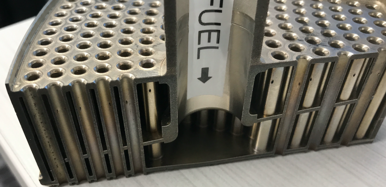
That is why the Monday review was a short list of trustworthy pictures, not a pile of unfinished cases:
- Fuel mixing — better mixing, lower NOx.
- Pressure drop across the combustor — higher drop is a less efficient turbine.
- Flow speed in the micromixer tubes — the flashback check.
Those pictures had to be trustworthy, and they had to arrive fast enough that the team could still iterate toward the 80% H₂ / 25 ppm NOx target.
What a CFD case involved
Computational fluid dynamics (CFD) is the numerical solution of the equations that govern fluid flow (Navier–Stokes), energy, and — for a combustor — species and chemistry, on a mesh that approximates the real geometry. The output is a field: velocity, temperature, composition, and derived quantities such as mixing quality and NOx.
We used Ansys Fluent for meshing and for solving the flowfield on novel combustors. A combustion case is not “run the solver.” It is a chain:
- Geometry — computer-aided design (CAD) of the combustor in Siemens NX.
- Mesh — discretize the volume. These cases were on the order of ~25 million cells. Meshing stayed manual: geometries kept changing, and at this scale someone has to fix local CAD discontinuities by hand.
- Boundary conditions — fuel flows, inlet temperatures and pressures, compositions, outlets, walls. If these are wrong or incomplete, the math problem is ill-posed and the expensive solve is wasted. There were hundreds of possible BC combinations; getting the set wrong, or typing it into Fluent wrong, burned the whole solve.
- Solve — Fluent marches the discretized equations until residuals and monitors (temperatures, mass imbalance, and the like) say the answer has settled. A journal file is a script of TUI commands that tells Fluent how to set up, run, and save the case — how you make a solve repeatable instead of clicking through the graphical user interface (GUI). Fluent’s Python application programming interface (API), FluentPy, existed, but it was not mature enough to bet the workflow on.
- Post-process — extract the pictures and numbers the design engineer actually uses: mixing, pressure drop, micromixer velocity, flame location, NOx, hot spots.
At the scale we were running, a single case used 512 CPU cores and 2 TB of RAM. Solver wall time started at about three days. Errors were not “rerun it after lunch.” They were days of HPC time and a stalled design loop.
The GE combustor results stay inside GE. The live field below is from a later project of mine: a two-dimensional (2D) Euler solve of a shock over a diamond airfoil, running in the browser. It is a much smaller problem, without chemistry — but it is the same species of picture the Monday meeting needed.
Live WebAssembly preview of the supersonic Euler solver. Click through for the full interactive demo and writeup.
The workflow I inherited
Raising that iteration rate is why I was brought onto the experimental team, headed by Michael Hughes.
The dedicated CFD contractor was running on average two cases per week on different meshes. The existing process was lightly automated, but it still depended on one person stitching the chain together by hand:
| Step | Who | What | Typical time |
|---|---|---|---|
| 1 | Team | A new design/iteration is brainstormed | — |
| 2 | Design engineer | Models the new design in CAD (Siemens NX) | 1–2 days |
| 3 | CFD contractor | Meshes the combustor (~25M cells); artisanal fix-up of CAD discontinuities | 1–2 days |
| 4 | Design engineer | Manually calculates boundary conditions a la carte | 0.5 days |
| 5 | CFD contractor | Takes instructions on boundary conditions and case setup | — |
| 6 | CFD contractor | Modifies previous journal files (TUI command sequences) | 0.5 days |
| 7 | CFD contractor | Launches the case and waits for the solve | ~3 days |
| 8 | CFD contractor | Manually post-processes results and delivers them | 1–2 days |
The cost of a mistake was the solve itself. Mess up the a-la-carte BC calculation and only notice after the case finishes: three days gone. Do the calculation correctly but type it into the journal wrong: another three days. The obvious improvements were engineering touch-time, error rate, and auditability — which is essential on government projects.
The bottleneck I promised to move — to the person who brought me onto the team, my manager, and the executive manager of gas power engineering — was manpower, not physics. CFD engineers should be doing design work, not tedious computer work.
Adoption had to be tactful. These were established engineers, world experts on combustion, and they do not take kindly to a young upstart rewriting their process. The original contractor was not pushed out; he became the mesh specialist, which is the part that still needed a human.
What I built
I planned the architecture first, from having done the work myself and from interviews with additional stakeholders. The surface area for CFD engineers had to shrink: specify intent, receive a consistent, provenance-tracked case, and get standardized outputs.
Orchestration and provenance
I audited 15 workflow orchestrators and settled on Prefect for parallel processing, native Python, a usable user interface (UI), and compatibility with locked-down corporate permissions. The tradeoff I lived with was Python’s multiprocessing under Prefect — running those jobs in parallel and viewing them on the Prefect API was a little buggy.
The workflow lived in Git, with a dev-unstable branch for active development, a dev branch, and continuous integration and continuous delivery (CI/CD) on commits to prod. Users pulled the latest version and ran with it. Every file the workflow created carried the git commit hash of the workflow version that produced it, so you could attest to provenance. All workflow files for a case went into that case’s output directory, and every case used the same folder layout, which made navigation and downstream scripting straightforward.
To keep that provenance honest, the workflow refused to run if the local working tree was dirty or if the checkout was not a commit that existed on the remote. Local tinkering that never got committed would otherwise produce unauditable cases. Command-line interface (CLI) flags could override the check for deliberate experiments; the default was fail-closed.
That hash was not decorative. Once, when a journal bug made cases only slightly off, I used git bisect to find where it was introduced, then identified and reran the affected cases.
The pipeline after meshing
Meshing stayed a specialist step. Everything after the mesh was orchestrated:
- Specify boundary conditions — users entered BCs for any number of cases in an Excel spreadsheet. The spreadsheet did not calculate anything; it was the input contract for the solver. GE runs on Excel. A YAML file would have been cleaner for me and worse for adoption: Excel kept world-class combustion engineers in their comfort zone.
- Solve boundary conditions — the system checked whether the BCs were well-posed. We predefined ~100 well-posed boundary-condition sets the solver could handle. When an engineer submitted inputs, a minimum-edit-distance search measured how far those inputs were from that list and either solved for the remaining quantities or told the user how to fully constrain the system. Against hundreds of BCs, that check was mostly convenience — stop people banging their heads against the wall. The real benefit was standardizing the BC calculations that used to be a la carte.
- Create journal files — a custom Python library took the now well-posed boundary conditions and wrote standardized Fluent journals — headers, dates, comment blocks, git commit hashes — into the case folder on the HPC environment.
- Launch jobs and monitor status — the workflow talked to our HPC API to submit Fluent jobs and watch them.
- Check case quality and post-process — on completion, the workflow launched a dedicated post-processing job that was the same for every case. Custom plots could still be done by hand. If the team later wanted additional information out of cases already run, you could modify the post-processing journal generation and relaunch post-processing on existing results — new information from work already paid for, rather than re-solving.
The well-posedness check is the same idea as the writeup below, just applied to a much larger system than PV = nRT:
%%{init: {"flowchart": {"useMaxWidth": false}}}%%
flowchart TD
    A[Excel boundary conditions] --> B[Well-posedness check]
    B --> C[Generate Fluent journal]
    C --> D[Submit and monitor on HPC]
    D --> E[Standard post-processing]
    E --> F[Mixing, pressure drop, micromixer velocity]
Because the workflow was consistent and repeatable, we could also run sensitivity studies on mesh count, CFD iterations, and solver settings, and cut CPU usage. We added the ability to seed similar cases with old solutions, which cut solve time further. Solver wall clock went from 72 hr/case to 48 hr/case.
Documentation and catching bugs before they cost a solve
A workflow that five non-software engineers are supposed to run needs an instruction manual, not a README only the author understands. I stood up a full documentation site with MkDocs, hosted on GitHub Pages inside GE. I wrote the best first version I could, then shadowed an engineer who was seeing it for the first time and watched where communication broke down — which step they skipped, which term was obvious to me and opaque to them, where the page and the actual CLI disagreed. Then I rewrote those spots and did it again. The docs were part of lowering the skill ceiling, same as Excel-as-input: meet people where they are, then make the path obvious.
We also implemented a full mock case test of the journal file: checkpoints ran through the journal while skipping the solution-iteration parts. That let us test journal changes without wasting days, and it ran on HPC as part of the prod CI/CD pipeline. Occasional journal errors still made it through. The incidence dropped dramatically.
What changed
I had promised to move the bottleneck from manpower to CPU power, and that is what happened.
Our team of five engineers — out of a combustion organization of hundreds — were using 37% of all of GE’s CPU cores by the time we were asked to throttle usage so other teams could continue. After the throttle we kept usage reasonable. CPU allocation did not become a hard design constraint; we were still doing huge amounts of analysis.
The workflow landed in the last few weeks of the first quarter of 2025 (Q1). Case submissions grew exponentially once it was in people’s hands. In Q1 and the second quarter (Q2) of 2025 it orchestrated 235 design cases, compared to ~22 in the same two quarters of 2024. That comparison is the 10×.
| Lever | Before | After |
|---|---|---|
| Case submission | ~30 minutes/case | seconds |
| Solver runtime | 72 hr/case (3 days) | 48 hr/case (2 days), plus further cuts when seeding |
| Post-processing | ~1 hr/case | seconds |
| Who could launch a job | 1 person regularly | 5 people on the team |
The runtime cut from 72 hr/case to 48 hr/case saved $15K per 100 cases in wasted compute, assuming $12.4K per 1 million CPU-hours and 512 CPUs per case.
The wall-clock saving was real. It was not the main point. Lowering the skill ceiling meant five people could launch jobs instead of one. Standard BCs and generated journals removed the two most expensive classes of human error. Versioned workflow code made debugging — git bisect included — and auditability tractable. And the consistent outputs are the dataset you need if you later want surrogate models on top of the loop: ease of job submission and post-processing is also what makes automatic optimization using machine learning (ML) and artificial intelligence (AI) possible.
Value
The program was at risk of slipping without this throughput. The added analysis capability was equivalent to ~10 contractors. CFD workflow automation provided $4.5 million (MM) in value from increased analysis and iteration capability, tied to the cost of the second half of the program that depended on this loop. That is program-unblocked value, not the $15K/100-cases compute saving.
I left the project before it was complete to join another team. The project lead’s own assessment was that the additional analysis capability — engineers iterating fast enough to hit the goals — is what rescued it.
If I rebuilt it now
The physics did not get cheaper. Meshing did not get faster; meshing stayed artisanal. What changed is that setup, provenance, launch, monitoring, and post-processing stopped being a craft process sitting in one contractor’s head.
Standard journals, standard folders, standard outputs, and a well-posedness check in front of a 512-core job meant the team could iterate on combustor geometry, mixing, pressure drop, and micromixer velocity instead of iterating on whether someone typed the TUI correctly. On a DOE-backed retrofit aimed at 80% hydrogen and 25 ppm NOx, that iteration rate was the product.
If I rebuilt this now, I would add a type checker on top of the linter and unit tests — Python lets too much through until runtime — re-evaluate orchestrators, and look hard at FluentPy instead of generating TUI journals, if the API is mature enough now. I would also make the fail-closed audit checks (clean working tree, commit on remote) louder about how to override them on purpose. The flags existed; they were easy to miss when you were already frustrated.